In the last post, we got the COR circuit working between the Baofeng and the repeater controller. In this post, we will continue with wiring up the Baofeng to the input side of the repeater and getting wiring looked at for output to the D710.
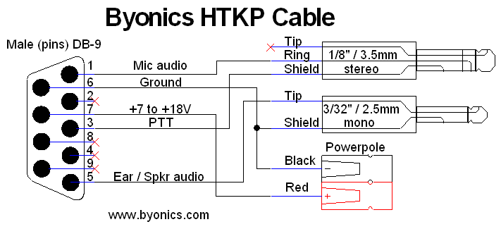 I am using the Byonics HTKP series HT cabling for getting audio out of the Baofeng UV-5R, and providing power to the repeater. In this case, I have the Powerpole connector on the cable. I have a DB9 female connector with pins 5, 6 and 7 passed through (the rest are unconnected). Pin 5 is the speaker audio, Pin 6 is Ground (linked between the shield on the headphone and the negative line on the powerpole), and Pin 7 is the +7 to +18V positive from power (red on the power pole).
The pinout on the ID-O-Matic IV has the pinouts as follows:
| PIN | DESCRIPTION |
|---|---|
| PIN 1 | Ground |
| PIN 2 | Power Input (6 to 20V) |
| PIN 3 | PTT Out (keys the transmitter in FM repeater applications) |
| PIN 4 | CW Out (on/off keyed Morse code output, NOT audio) |
| PIN 5 | Beacon Indicator output (active when beacon is being transmitted) |
| PIN 6 | Reset (ground to reset the ID-O-Matic IV) |
| PIN 7 | COR Input |
| PIN 8 | Receiver audio input |
| PIN 9 | ID Indicator (active when Morse ID is being transmitted) |
| PIN 10 | ALT MSG input (selects the alternate CW ID transmitted) |
| PIN 11 | Audio Out (Morse ID and Tone output) |
| PIN 12 | GROUND |
I put a 1K resistor between the pin 2 and 7 on the ID-O-Matic, then brought in the COR line from the Baofeng to PIN 7. The ID-O-Matic is now setup to receive power and audio from the Baofeng and Byonics cable.
Now, to get audio out of the repeater to the D710 is pretty easy. The D710 has a documented information about its microphone port. It is RJ45, which makes it pretty easy to come up with a cable for.
On the Kenwood RJ45 connector, Pin3 is Ground, Pin4 is PTT, Pin5 is Mic Ground, Pin6 is Microphone input. Output from other audio sources should have a register on the mic line of the value 470. It should also be shunted to Pin5 via a resistor of value 3.9. I get these values from the Sky Commander manual for the D710G. With this fairly simple wiring, we have the following:
| ID-O-MATIC | D710 |
|---|---|
| PIN 3 (PTT OUT) | PIN 4 (PTT IN) |
| PIN 11 (Audio Out) | PIN 6 (MIC) |
| PIN 12 (Ground) | PIN 5 (Mic Ground) |
Once these are all hooked up, the repeater should work. The kenwood will key up when the green LED turns on with the baofeng.
I ended up moving all of this to a board with solder on plug connections from Sparkfun for the RJ45 and DB9 Connectors I am using. Here is the board while being created:
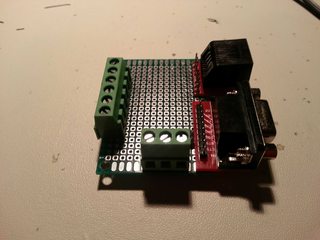
This allows me to put the repeater in a small box and supply power / control lines to the radios via standard connectors which are already on my cables.
Stay tuned for information about duplexers in Part 4.